| HARK version 1.1.0 Document |
| HARK version 1.1.0 Document |
From the multi-channel complex spectrum that is output from the MultiFFT node, generate the correlation matrix for a sound source when specified by the input flag.
None.
In what case is the node used?
The scenario for usage is same as CMMakerFromFFT node; for details refer to the CMMakerFromFFT node. The main difference is in the calculation of the correlation matrix. In the CMMakerFromFFT node, the correlation matrix is updated at a fixed period (PERIOD), but in this node it is possible to generate a correlation matrix for a specified section according to the flag value obtained from the input terminal.
Typical Examples
Figure. 6.14 shows the usage example of CMMakerFromFFTwithFlag node. The INPUT input terminal is connected to the complex spectrum of the input signal calculated from a MultiFFT node. The type is Matrix<complex<float> > type. ADDER_FLAG is int type or bool type of input, and controls the events related to the correlation matrix calculation. Event control details are given in the Module details section. This node calculates and outputs the correlation matrix between channels for each frequency bin from the complex spectrum of the input signal. The output type is Matrix<complex<float> > type, but to handle a correlation matrix, convert the three dimensional complex array to a two dimensional complex array and then output.
![\includegraphics[width=.8\textwidth ]{fig/modules/CMMakerFromFFTwithFlag.eps}](images/img-0150.png)
Parameter |
Type |
Default |
Unit |
Description |
NB_CHANNELS |
8 |
Number of channels |
||
LENGTH |
512 |
Frame length |
||
MAX_SUM_COUNT |
100 |
Maximum number of normalized frames of a CM |
||
ENABLE_DEBUG |
false |
ON/OFF of debugging information output |
Input
Matrix<complex<float> > type, the complex spectrum expression of an input signal with size  .
.
int type or bool type. Controls the events related to correlation matrix calculation. Refer to the Module Description section for event control details.
Output
Matrix<complex<float> > type. A correlation matrix for each frequency bin. An  -th order complex square array correlation matrix outputs
  items. Matrix<complex<float> > contains rows corresponding to frequency ( rows), and columns containing the complex correlation matrix (
 columns across).
Parameter
int type. Number of channels in the input signal. Equivalent to the order of the correlation matrix. Must be matched with the order of the former correlation matrix used. Default value is 8.
int type. Default value is 512. FFT points at the time of Fourier transform. Must be matched with the former FFT length values.
int type. Default value is 100. Specifies the maximum number of average smoothed frames when calculating the correlation-matrix. This node can control the number of average smoothed frames of a correlation matrix by ADDER_FLAG. For this reason, if the ADDER_FLAG is always 1, only addition of correlation matrix is performed and there will be no output at all. Thus, when it reaches the maximum count of average smoothed frames by correctly setting the MAX_SUM_COUNT, the correlation matrix will be output forcefully. To turn OFF this feature specify MAX_SUM_COUNT = 0.
bool type. Default value is false. When true, the frame number is output to the standard output at the time of generating the correlation matrix.
The algorithm for the CMMakerFromFFT node and correlation matrix calculation is the same. Refer to the Module description of the CMMakerFromFFT node for details. The difference with CMMakerFromFFT node is that the average smoothed frames of a correlation matrix can be controlled with the ADDER_FLAG input terminal flag.
In the CMMakerFromFFT node, the correlation matrix was computed with the following formula with the number of frames specified by PERIOD.
 |
(4) |
This node generates a correlation matrix based on the value of the ADDER_FLAG as follows.
When ADDER_FLAG changes from 0 (or false) to 1 (or true)
The correlation matrix returns to zero matrix and PERIOD returns to 0.
PERIOD = 0
where  represents the zero matrix.
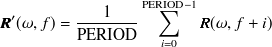
When ADDER_FLAG is 1 (or true)
Add the correlation matrix.
PERIOD = PERIOD + 1
When ADDER_FLAG changes from 1 (or true) to 0 (or false)
Take the average of the added correlation matrix and output it to OUTPUT.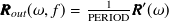
When ADDER_FLAG is 0 (or false)
Keep the correlation matrix generated in the end.
Here, is the correlation matrix that is output from the OUTPUT terminal. In other words, the new correlation matrix will be stored in in phase C).
| HARK version 1.1.0 Document |
