Recording TSP Response using RASP-24
Table of Contents
1. Overview
2. Equipment
3. Sound Source Position Setting
4. Setup PC IP Address to Static Address
5. Recording Procedure
1. Overview
This manual covers a step by step procedure for recording TSP response using a customized microphone array connected with RASP-24 in a sample set-up.
2. Equipment
This section provides information on equipment used in this manual and how to connect the recording devices.
- Microphone Array
RASP-24 is a compact 24-bit A/D and D/A acoustic input/output system capable of multichannel acoustic output.
- Number of channels: 16 channels (basic configuration)
- Microphone layout(custom): A circular layout with a 45 mm radius and 22.5 degree intervals (Figure1)
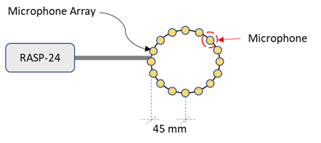
Figure 1. Microphone array
A/D: RASP-24
- Product Information:
https://www.sifi.co.jp/en/solution/product.php?content_id=7&category_id=4&page_name=RASP-24 - Device type: LAN
- Recording type: Synchronized playing and recording
- Software
- Robot Audition Open Source Software HARK version 2.4.0.2
- HARK-WIOS version 0.1.2
- Digital Audio Editor: Audacity
- Other Equipment
- Speaker for playing back TSP signals
- LAN cable
- Additional stationery tools
- Tape for marking
- Ruler/Measuring Tape/Protractor for measuring
- Wiring Diagram
Figure 2 shows how to setup the equipment when using RASP-24.
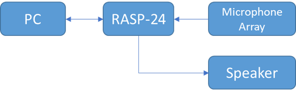
Figure 2. Wiring Diagram for the Equipment Setup
- Connect the microphones to the RASP-24
- Connect RASP-24 into PC LAN port using a LAN cable
- Connect RASP-24's Audio output port to the Speaker.
3. Sound Source Position Setting
This section provides directions how to set up the recording environment according to the following assumptions:
- Number of sound source positions: 12
- Layout: Circular with a radius of 1 meter
- Elevation to the microphone positions: 0 degree
- Find a room to perform TSP recording. The following recording conditions are preferable:
- Noise should be as low as possible.
- The room environment should be as similar as possible to where the transfer function is to be used.
- With a piece of tape or a sticky paper, mark a suitable position where the microphone array will be placed. For a circular setup, choosing the center of the room as illustrated in Figure 3 will provide enough space for marking all the positions. Place the microphone array on the marked position.
- As shown in Figure 4, draw a circle with a radius of 1 meter around the microphone array. Choose a starting point and mark it as 0°. Put a mark on every 30° interval in a counter clockwise direction from the starting point using a tape or a sticky paper. Measure the angles using a protractor. Write the angle value on the maker.
- Place the speaker on the starting point marked as 0° as shown in Figure 4.
- Set the speaker at the same height with the microphone array as shown in Figure 5.
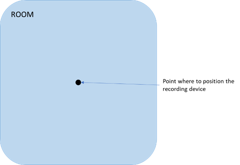
Figure 3. Recording Room [Top View]
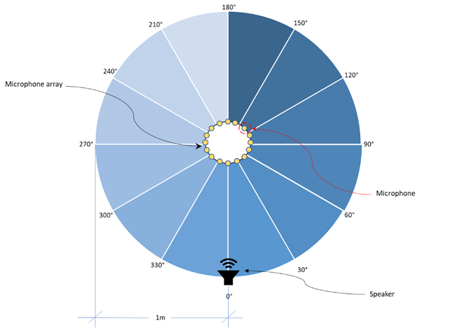
Figure 4. Recording Environment Set Up [Top View]
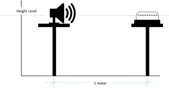
Figure 5. Recording Environment Set Up [Side View]
4. Setup PC IP Address to Static Address
This section will provide the steps on how to set the PC's IP address to a static IP address which will allow communication with RASP-24.
- Open Control Panel and choose 'Network and Internet'. Figure 6 shows where the 'Network and Internet' is located.
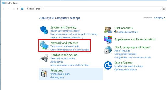
Figure 6. Settings for Network and Internet - After doing the previous step, the window shown in Figure 7 will be displayed. Click 'Network and Sharing Centre'.
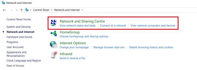
Figure 7. Network and Sharing Centre - After clicking the 'Network and Sharing Centre', click 'Change Adapter Settings' located on the left side of the window as shown in Figure 8.
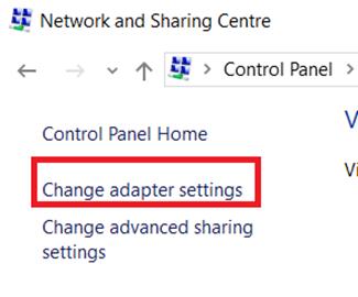
Figure 8. 'Change Adapter Settings' of Network and Sharing Centre - After clicking 'Change Adapter Settings' in Step 3, the window shown in Figure 9 below will be displayed. Right click on Ethernet and choose 'Properties'.
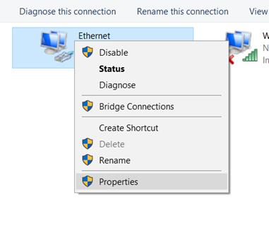
Figure 9. Properties for Ethernet - Ethernet properties window will be displayed after completing Step 4. Click on 'Internet Protocol Version 4 (TCP/IPv4)' and click on 'Properties' as shown in Figure 10.
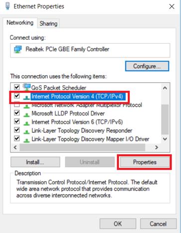
Figure 10. Properties for IPv4 - IPv4 Properties window will be displayed. Figure 11 shows the IPv4 Properties window. Choose 'Use the following IP address:' and set the IP address to 192.168.33.25 since the default IP address of RASP-24 is 192.168.33.24.
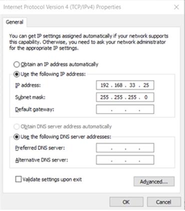
Figure 11. Setting of static IP Address
5. Recording Procedure
This section provides detailed procedures focused on recording the TSP signal.
- Connect the devices as illustrated in Figure 2 in Section 2.
- Prepare the recording environment as discussed in Section 3.
- Prepare the PC to connect to RASP-24. The PC should have HARK-WIOS and Audacity installed.
- Make sure you have the TSP Signal in your PC. It should be found in the HARK-WIOS install directory.
- PC's IP address needs to be set to a static address to communicate with the RASP device. Follow the steps in Section 3 to set the PC's IP address to a static address.
- Open command prompt. To do this, press [Windows key] + R. The window shown in Figure 12 below will pop up. Then type 'cmd' and press enter.
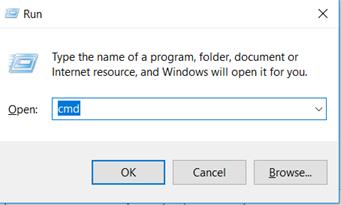
Figure 12. Dialog box for "Run" in Windows - Inside the command prompt, ping the RASP-24's IP address. To do this, run the following command:
ping 192.168.33.24 - Check if the address is valid and is sending a reply. See Figure 13 below for an example of an address that is sending a reply. Once everything is ready, proceed to the actual recording of the TSP WAV file.
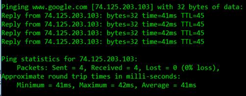
Figure 13. Sample reply after pinging a valid IP address - Open command prompt in Windows and run the following command:
wios -v 2 -w 2 -s -x 2 -d {ip} -i {tsp audio input} -o {output file path} -G 3 -e 24 -c {number of channels to use} -f 16000
- {ip} - ip address of the device connected via network cable. For RASP-24 default is 192.168.33.24
- {tsp audio input} - the file path of the TSP signal to use. For Windows, use tsp24bit_2ch.wav that can be found in the installation directory.
- {output file path} - the file path of the tsp audio output.
- {number of channels to use} - the number of channels to use.
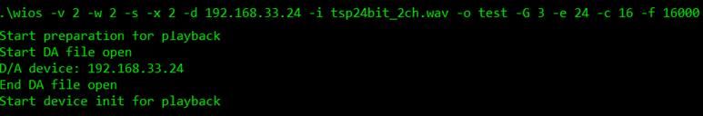
Figure 14. Running WIOS in Windows command prompt - The RASP and WIOS will handle the playback and recording of the TSP signal.
- Open the output wav file with Audacity. Output file path is the one indicated in Step 9 {output file path}.
- Check if the wave height is too short or too long. Too short does not satisfy the requirement whereas too long indicates that some of signals have been clipped. If either state is confirmed, adjust GAIN parameter in WIOS command. To adjust the GAIN parameter, see Figure 15.
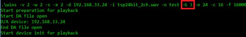
Figure 15. Gain parameter in WIOS command - Please note that the TSP response has been considered successfully recorded if the scale of the wave ranges between positive .5 through.05 and negative .5 through .05 as highlighted in Figure 16. If the wave is lower or greater then this values, you can either increase the volume of the loudspeaker or increase the Gain.Figure 16 is an example sound wave form whose height is not too long nor too short.
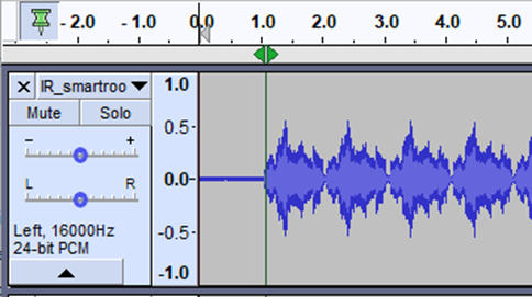
Figure 16. Normal Sound Wave - If the sound wave looks okay, choose at least one channel and view it in Spectrogram. To do this, click on the wav filename and preferred channel as shown in Figure 17 to display options and then select Spectrogram.
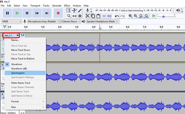
Figure 17. Recorded TSP responses in wave view - Figure 18 shows a Spectrogram display of a recorded TSP.
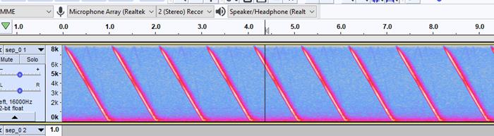
Figure 18. Recorded TSP in spectrogram view in Audacity - If there are noises captured like ones enclosed with a black rectangle in Figure 19, redo the recording from Step 9 for this specific angle.
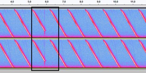
Figure 19. Captured Noise in spectrogram view in Audacity - If the wav file looks fine, rename the generated wav file with the recording location angle in the filename so it will not get overwritten. Table 1 shows the example filenames corresponding to each recording and angle.
Table 1. Filename ExamplesAzimuth of the speaker where TSP was played in the polar coordinates that were defined in Section 3. Filename 0° D_000.wav 30° D_030.wav 60° D_060.wav ... ... 330° D_330.wav - Move the speaker to the next marked position in a counter clockwise direction as shown in Figure 20 and do the recording again starting from Step 9 to Step 17. Repeat the recording for all 12 marked angles. There should be 12 successful wav files at the end of this activity.
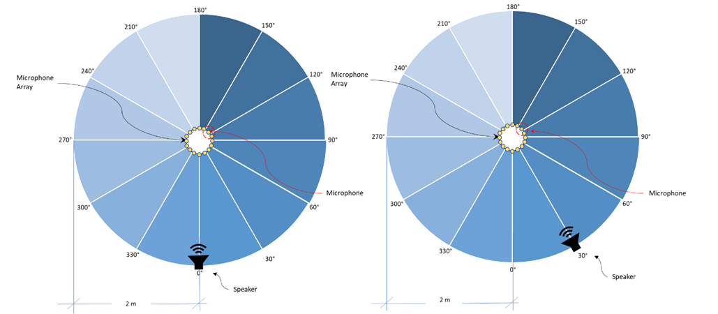
Figure 20. Speaker Positions [Top View]
---- End-----