Overview
HARKTOOL5-GUI is a web browser based graphical user interface that generates and visualizes transfer function for sound source localization and separation.
Using HARKTOOL5-GUI, you can do the following things:
Create, edit and visualize microphone array coordinate file
Create, edit and visualize sound source coordinate file
Generate and visualize transfer function
Getting Started
Dependent software
HARKTOOL5-GUI depends on following softwares. Please install them before you install HARKTOOL5-GUI.
node.js (An application server)
For Windows users: Download v10.x from https://nodejs.org/en/download/releases/
For Ubuntu users: Install v10.x from https://github.com/nodesource/distributions
- Google Chrome
Install
For Linux users
Add HARK repository. For details, see https://www.hark.jp/install/linux/
Install HARKTOOL5-GUI. Execute
sudo apt install harktool5-gui
For Windows users
https://www.hark.jp/install/windows/ to install Hark for Windows and dependent software.
Step 1: Open the HARKTOOL5-GUI
For Linux users
On the terminal, run harktool5_gui. Then, chrome browser will be opened immediately.
For Windows users
On the Start Menu, Click HARK > HARKTool. Then, chrome browser will be opend immediately.
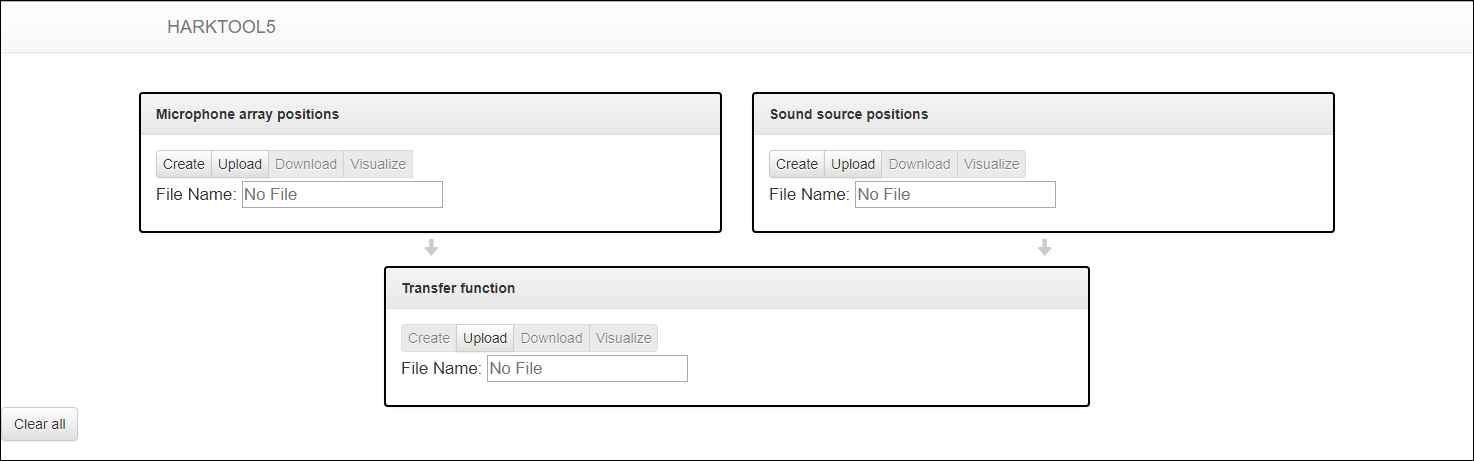
Step 1: The initial screen
Step 2: Create the microphone array coordinate file
If you want to use the old microphone location information file, see Migration of microphone location information file.
Click “Microphone array positions” > “Create”.
Select the coordinate model.
Input parameters. Distance unit is meter.
General parameters
- Position Type
Fixed “microphone”
- Output File
Specifies the Output File name
Clicking the “Create” button at the bottom of the screen creates a microphone array coordinate file and displays the 3D graph on the right.
Click on the “Go back to the top page” link or the “HARKTOOL5” title on the screen and return to the top screen.
The created microphone array coordinate file can be downloaded by clicking “Microphone array positions”> “Download”.
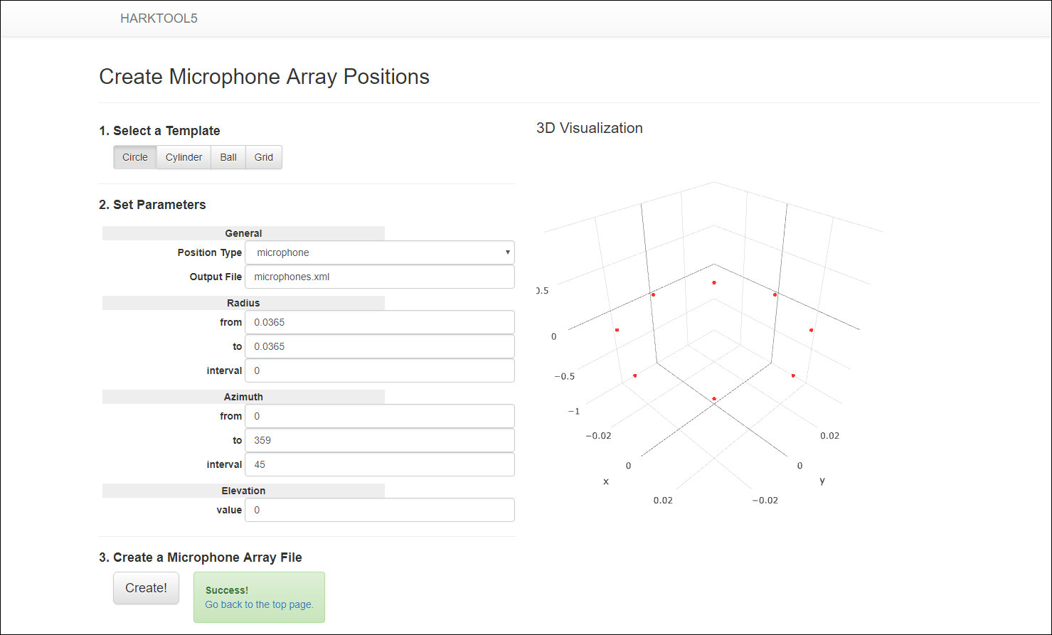
Step 2: After creating microphone array coordinate file
Step 3: Create sound source coordinate file
If you want to use the old TSP response list file, see Migration of TSP response list file.
Also, if you want to use the old impulse response list file, see Migration of impulse response list file.
Click “Sound source positions” > “Create”.
Select the coordinate model.
Input parameters.
General parameters
- Position Type
Select “tsp” when using the recorded TSP, otherwise select “impulse” when using impulse response (wav format)
- Wav File Path
Specifies the storage path of the recorded TSP file or impulse response (wave format). The following chart represents the templates and its respective units of measurement.
RADIUS ( Unit m )
ELEVATION ( Unit deg )
AZIMUTH ( Unit deg )
X_AXIS ( Unit mm )
Y_AXIS ( Unit mm )
Z_AXIS ( Unit mm )
HEIGHT ( Unit mm )
- Output File
Specifies the Output File name
- Use Channels
Enumerate the microphone channels to use, separated by commas. A blank means use all channels
Neighbors parameters
- Algorithm
Algorithm type. Fixed “NearestNeighbor”
- Maximum Number
Maximum number of neighbors each position can have
- Threshold
Threshold for neighbor decision (unit m)
Clicking the “Create” button at the bottom of the screen creates a sound source coordinate file and displays the 3D graph on the right side.
Click on the “Go back to the top page” link or the “HARKTOOL5” title on the screen and return to the top screen.
The created sound source coordinate file can be downloaded by clicking “Sound source positions”> “Download”.
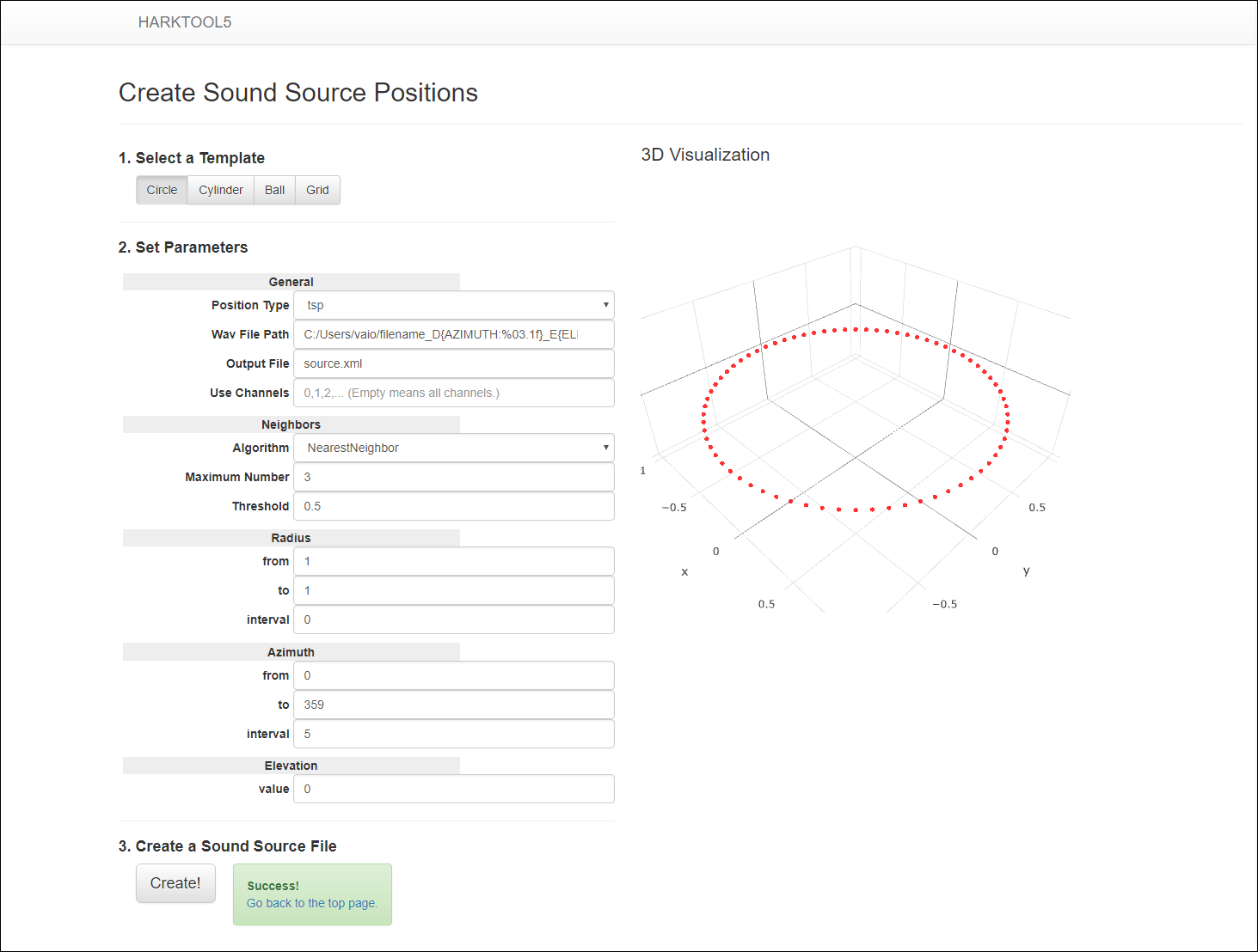
Step 3: After creating sound source coordinate file
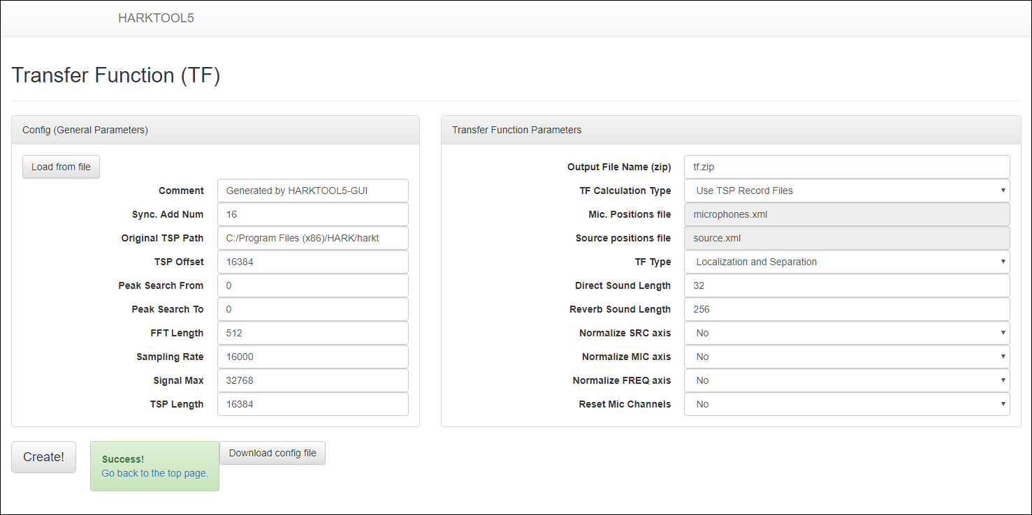
Step 4: Create the transfer function file
When the microphone array coordinate file and the sound source coordinate file are prepared, a transfer function file can be created.
Click “Transfer function” > “Create”.
Input Config (General Parameters) when it is needed.
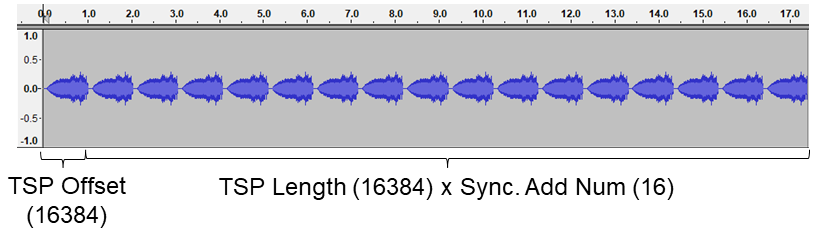
- Sync. Add Num
The count of consecutive replays of TSP signal at the time of TSP signal recording
- Original TSP Path
The filepath of the TSP signal of one cycle used for recording
- TSP Offset
Start position to use the recorded file for transfer function calculation (unit sample 0 origin)
- Peak Search From
Start position to search for a peak when calculating transfer function (unit sample 1 origin)
- Peak Search To
End position to search for a peak when calculating transfer function (unit sample 1 origin)
Note
When 0 is specified for Peak Search, a peak is searched for in the range of all samples.
It considers the searched peak position as direct sound. Peak Search is used to ignore (delete) the reflection, for example, in the case of the refraction being louder than the direct sound.
- FFT Length
The number of bins in the discrete frequency expression of the transfer function
- Sampling Rate
Sampling frequency of the transfer function
- Signal Max
The value of the maximum amplitude
- TSP Length
The length of one recorded TSP signal
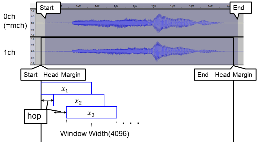
The following figure shows the correspondence between the waveform of Typical TSP recording (17 times continuous TSP playback and its synchronized recording by wios) and the Config parameter.
Input Transfer Function Parameters when it is needed.
- Output File Name (zip)
Specifies the output file name of the Transfer Function
- TF Calculation Type
- Select method to calculate transfer function (Depending on the Position Type chosen in Step 3, some options may not be displayed.)
Use Impulse Response Files: Calculate transfer function from impulse response file
Use TSP Record Files: Calculate transfer function from TSP recorded file
Use Mouth TSP Record Files: Calculate transfer function from TSP recorded file by Transfer Function Estimation Using Complex Regression Model (New feature of HARKTOOL5)
Use Geometric Calculation: Calculate transfer function by geometric calculation
- TF Type
Whether to include for localization or separation for transfer function file
- Direct Sound Length
Number of samples consider as direct sound
- Reverb Sound Length
Number of samples consider as reverberation
- Normalize SRC axis
Whether to normalize the sound source axis of the transfer function
- Normalize MIC axis
Whether to normalize the microphone channel axis of the transfer function
- Normalize FREQ axis
Whether to normalize the frequency axis of the transfer function
- Reset Mic Channels
Whether or not to reset the transfer functions microphone channel selected in “Create sound source coordinate file”. It will reset the channels selected starting from 0.
Note
In the case you choose to reset, it will make the transfer function compatible with HARKTOOL4.
Clicking the “Create” button at the bottom of the screen creates a transfer function file.
Click on the “Go back to the top page” link or the “HARKTOOL5” title on the screen and return to the top screen.
Step 4: After creating transfer function file
By clicking “Transfer function” > “Visualize”, the created transfer function file can be confirmed in 3D graph.
- TF type
Select transfer function(localization/separation) to be displayed
- Domain
Select X axis (frequency/time) of graph
- Z Axis
Select the type of Z axis (only in frequency domain)
Amplitude: Display amplitude spectrum
Amplitude in dB: Display amplitude spectrum in decibels
Phase: Display phase spectrum
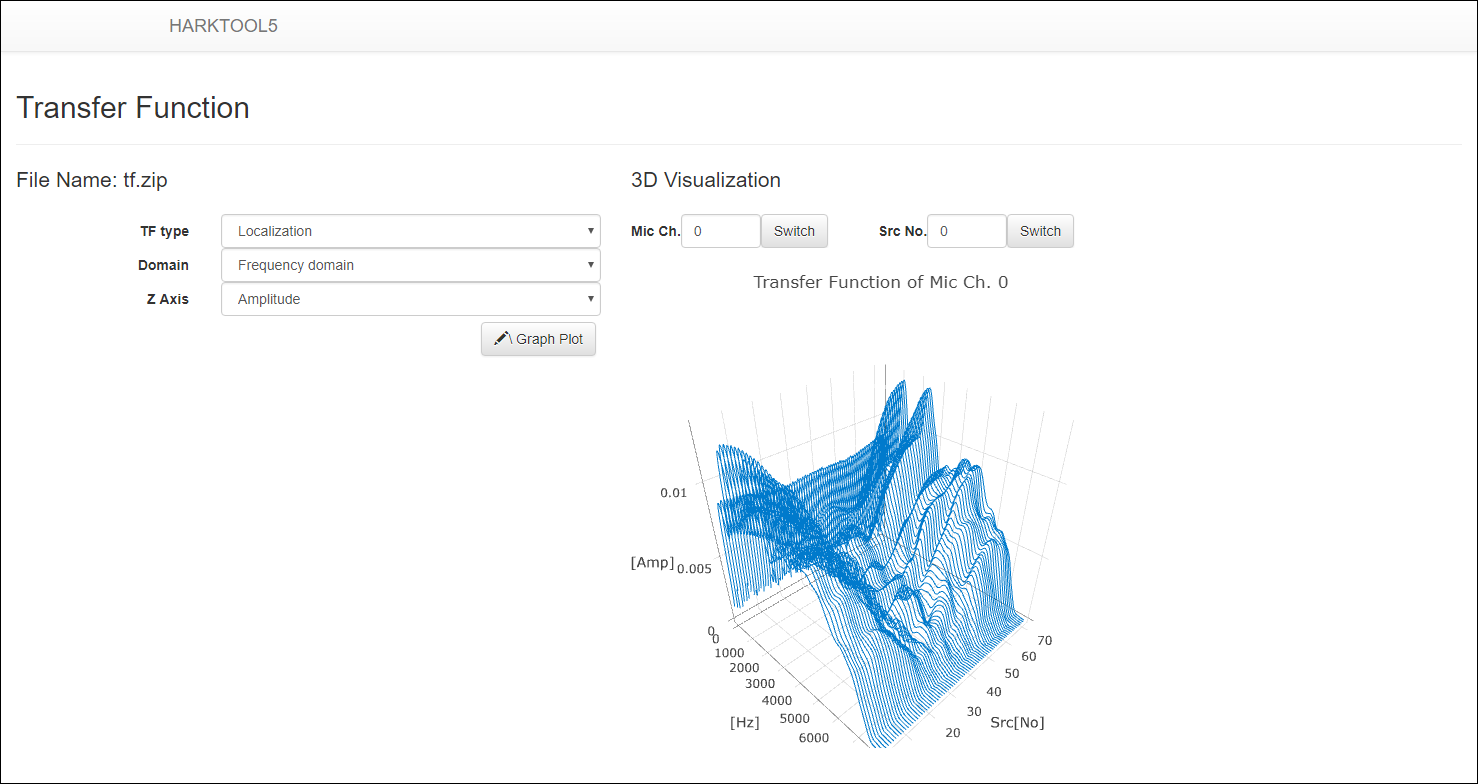
Display transfer function
By clicking “Transfer function” > “Download”, the created transfer function file can be download.
Transfer Function Estimation Using Complex Regression Model
This method can estimate transfer functions from the recorded multi-channel acoustic signals using a complex regression model. The characteristics of the method are as follows:
It is not necessary that playing and recording are performed synchronously.
Any acoustic signal like human voice can be selected (no need to use TSP).
The relative transfer function from the reference microphone channel is obtained.
The transfer function is estimated only for frequencies which are included in the emitted signal.
To use Transfer Function Estimation Using Complex Regression Model, select Use Mouth TSP Record Files for TF Type in Step 4: Create the transfer function file. The following parameters will be added, so input when it is needed:
- Mouth TSP Start
Start position to use the recorded file for transfer function calculation (unit sample 0 origin). This is an alias for Config > TSP Offset.
- Mouth TSP End
End position to use the recorded file or transfer function calculation (unit sample 0 origin)
- Mouth TSP mch
Reference microphone channel
- Mouth TSP hop
Shift length (unit sample) at transfer function calculation
- Mouth TSP Head Margin
Margin at the head position of the impulse response (unit sample). If there is a microphone channel from which the direct sound arrives earlier than the mch, a corresponding margin is needed. In the usual case, it is desirable to set a margin of about 128 (= FFT Length / 4).
Transfer Function Estimation Using Complex Regression Model parmeters
Algorithm
The input signal S, the impulse response H, and the output signal X are expressed in the frequency domain by the following numerical formula:
Since it is the same sound field for different time frame \(t = 1 \cdots N\), it is expressed by the following determinant:
Migration from HARKTOOL4
Install Python 2.7 or later.
Download the migration tool from https://www.hark.jp/downloads/harktool5migrationtool.zip .
Extract it to working directory.
Migration of microphone location information file
Execute
python conv4mic.py <microphone location information file> <output file>.
e.g.)
python conv4mic.py miclist.xml microphones.xml
The output file can be loaded from “Microphone array positions” > “Upload” of HARKTOOL5-GUI.
Migration of TSP response list file
Execute
python conv4src.py <TSP response list file> <output file>.
e.g.)
python conv4src.py tsplist.xml source.xml
The output file can be loaded from “Sound source positions”> “Upload” of HARKTOOL5-GUI.
Migration of impulse response list file
Execute
python conv4src.py <impulse response list file> <output file>.
e.g.)
python conv4src.py implist.xml source.xml
The output file can be loaded from “Sound source positions”> “Upload” of HARKTOOL5-GUI.
Since the `` flt2multiwav.txt`` file is also output, the flt file is converted to a wav file by executing the command output in the file.